Klipper Input Shaping for Ender 3 - All You Need to Know

Klipper’s Input Shaping functionality stands out particularly well owing to its excellent execution and utility. It lets you print at higher speeds while ensuring that the print quality is not affected due to the 3D printer’s fast movements. It’s probably one of the most sophisticated and our favorite features in the Klipper firmware.
Yet, for several users, Input Shaping is still a mystery and a concept that seems too technical and complex to understand.
In this article, we’ll break down Input Shaping in Klipper for you and help you understand how it can assist you in achieving excellent print results. We’ll start by understanding it in detail and learn more about how it works in Klipper. We’ve also included a step-by-step guide that’ll help you configure Klipper for your 3D printer. In this guide, we will tune input shaper on an Ender 3 3D Printer, but this guide is relevant for similar 3D printers as well.
Let’s start shaping our Klipper 3D printers!
Why Do You Need Input Shaping?
Any motion on your 3D printer leads to a certain amount of vibration in your printer’s frame. In most cases, your printer’s frame is rigid enough to absorb these vibrations and prevent any side effects on the 3D prints.
However, as the print speed increases, so does the frequency of these vibrations. The vibrations can get quite tense at higher print speeds and shake the printer’s frame. While you might not notice the rattling of the printer’s components, the side effects of these high-frequency vibrations can be evident in your 3D prints.
Ringing/Ghosting effects on the surface of your 3D prints are a direct result of an unstable 3D printer frame. These artifacts are easily noticeable on your print’s surface and ruin the quality of your 3D prints.
Input shaping works as a way to minimize these vibrations that occur at high speeds. Instead of tightening your printer’s frame, it optimizes the stepper motor movements to produce minimal vibrations, even at high speeds. The result is a smooth acceleration of your printer’s moving parts, leading to fewer vibrations and better print quality.
Let’s understand the logic and working behind Input shaping.
Input Shaping In Klipper
Input Shaping is a common technique to reduce the vibration produced in a motion system. It’s an open-loop control method that finely controls the input signal passed on to the stepper motor.
The input/commanding signal generated is fine-tuned to cancel out the vibrations it might cause in your 3D printer. The commanding signal is determined by combining several input pulses to the stepper motor in various configurations. These configurations are termed Input Shapers.
For example, an input shaper might consist of a combination of short and long impulses. In contrast, another one might include short but consistent bursts of input signals. These Input Shapers result in varying levels of motion smoothing, owing to their different build.
In Klipper firmware, you can test various Input Shapers at various frequency levels. It helps you determine which input shaper is best for your 3D printer. This working gives you the flexibility to choose from various options, and makes Klipper’s Input Shaping compatible across several 3D printer configurations.
Dmitry Butyugin first implemented Input Shaping support in Klipper firmware in the August 2020 update. With the help of an ADXL345 accelerometer, Dmitry found a way to measure the printer’s resonant frequency and determine the Input shaping parameters.
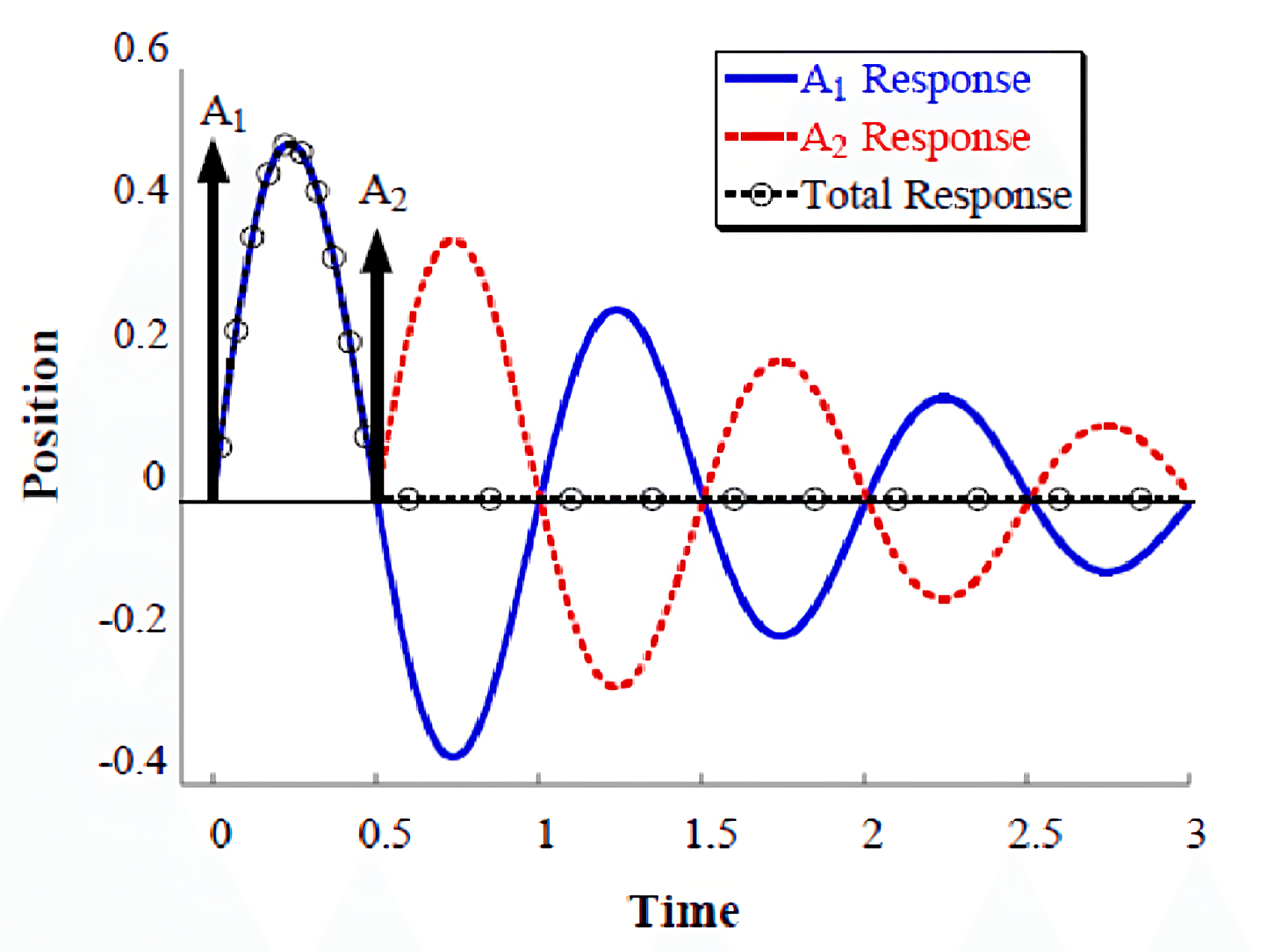
Photo Courtesy Quoc Chi Nguyen via Researchgate
Klipper calculates Input shaping using the Raspberry Pi as the secondary MCU to connect an ADXL345 accelerometer and control the 3D printer. The printhead and build plate vibrate at various frequencies as the Pi sends different Input shaper signals. In the end, the Pi calculates all the test data and recommends you the preferred Input Shaper settings.
Alternatively, you can tune Input Shaping via a manual method. It’s slightly less accurate but is easy and quick to perform.
The mathematics and computing involved in Input shaping are pretty technical, and you don’t need to go over it unless you want to learn it in extreme detail.
Now that we have a basic understanding of Input shaping let’s begin setting it up in Klipper firmware.
How to Configure Input Shaping in Klipper?
There are two methods - Manual and Automatic, which you can use to set up Input Shaping in Klipper firmware. We’ll go over both these methods in detail.
Manual Input Shaping In Klipper
The manual method to configure Input shaping is relatively straightforward and needs no external component. You have to manually measure the oscillations on a ringing tower designed to exaggerate vibrations' effects on your 3D prints. Let’s go over the step-by-step procedure of manually setting up Input Shaping in Klipper.
What You’ll Need
- Ringing Tower STL
- Vernier caliper or measuring scale
Slicer Configuration
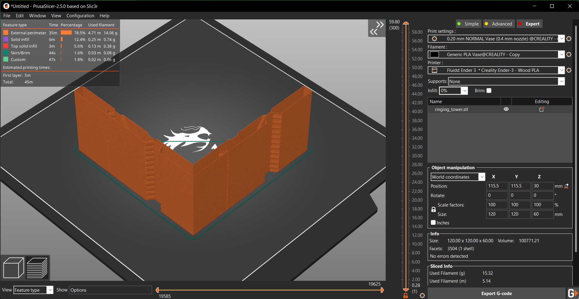
- Set the layer height to 0.2 or 0.25 mm.
- Zero Infill and Top layers.
- Set the Perimeters to 1 or 2 maximum with a base height of 1-2 mm. If you want even better results, try using the vase mode in your slicer.
- Set the external perimeter printing speed around 80-120 mm/s. It’ll make the printer vibrate more than usual, resulting in better calibration.
- The minimum layer time should be at most 3 seconds. A lengthy layer time will slow the print speed and skew the test results.
- Disable any Dynamic acceleration or acceleration limits in the slicer.
- Print the model as it is. Do not try to change its orientation in the slicer. The X & Y marks will later be used to identify the resonance for that particular axis.
Klipper Settings
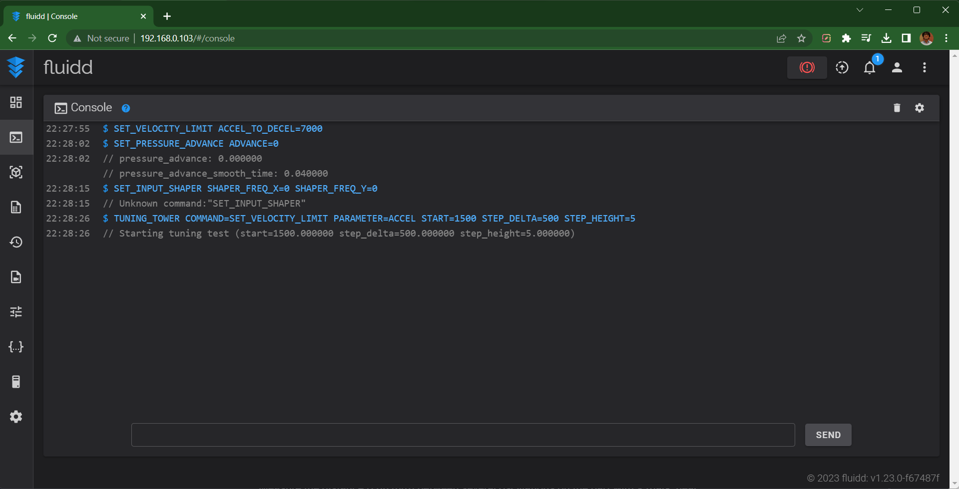
- Increase the max_accel_to_decel by issuing the following command in Klipper’s command terminal:
SET_VELOCITY_LIMIT ACCEL_TO_DECEL=7000. - Set the Pressure Advance to Zero by inputting
SET_PRESSURE_ADVANCE ADVANCE=0. - Disable any previous Input Shaper settings by executing
SET_INPUT_SHAPER SHAPER_FREQ_X=0 SHAPER_FREQ_Y=0 command. If you get an ‘Unknown command’ error, it indicates you don’t have any previous settings. Proceed to the next step. - Execute the command:
TUNING_TOWER COMMAND=SET_VELOCITY_LIMIT PARAMETER=ACCEL START=1500 STEP_DELTA=500 STEP_HEIGHT=5. This command will increase the acceleration value every 5 mm, till the final limit of 7000 mm/s is achieved.
Measuring Print Resonance
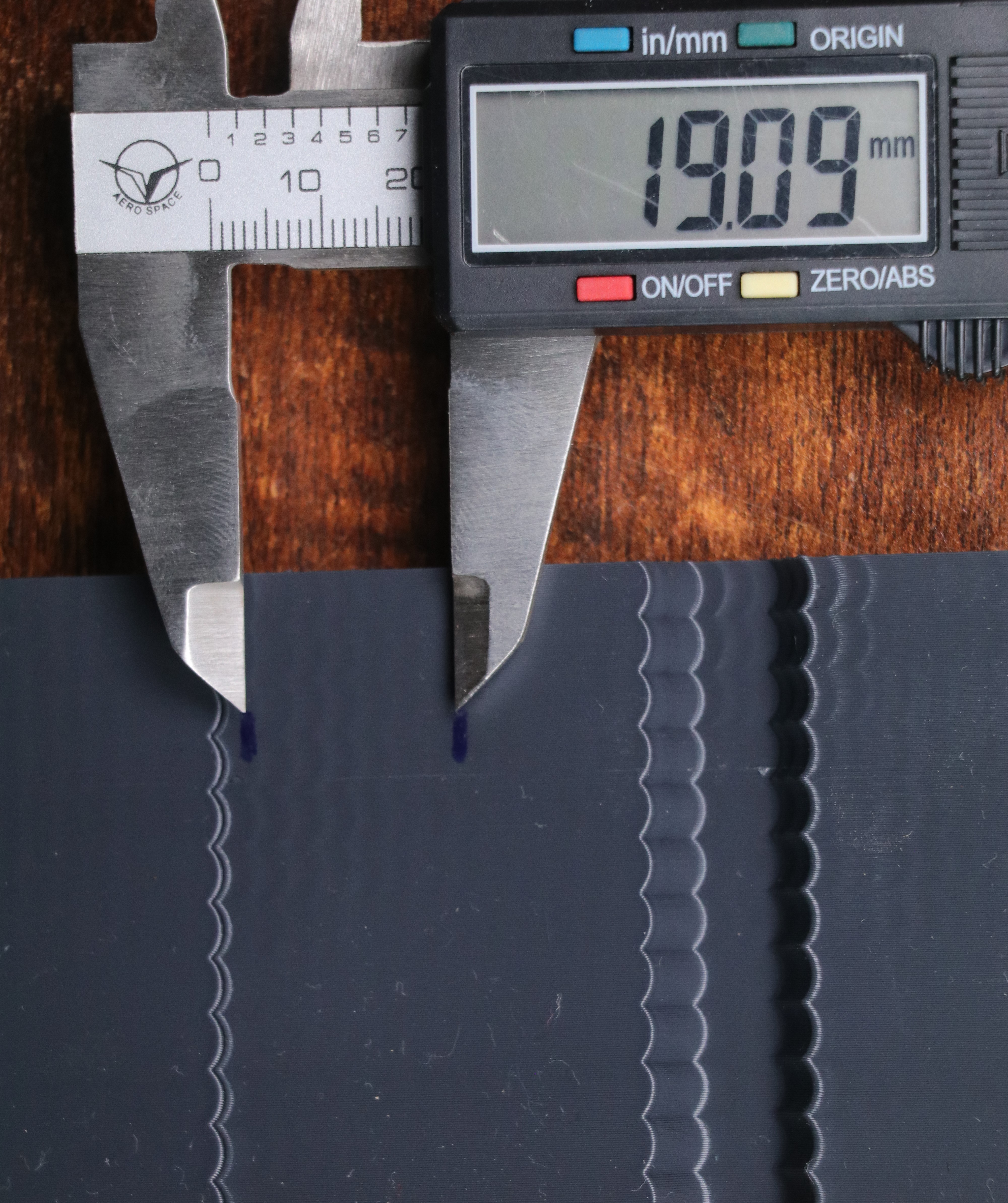
- Use the X and Y marks on your model as a reference. The X mark denotes the side for the X-axis configuration, while the Y mark indicates the side for the Y-axis configuration.
- Use a vernier caliper or measuring scale to measure the distance between multiple oscillations. You can skip the first couple of oscillations.
- Mark a starting point, and measure the distance between 6-8 oscillations on your print’s surface.
- Calculate the ringing frequency of the X axis by using V · N / D (Hz). V is the velocity for outer perimeters (mm/sec). N is the number of oscillations, and D is the distance between them. For example, if you marked eight oscillations and printed the test model at 100 mm/sec velocity, the frequency is 100 * 8 / 19.00 ≈ 42 Hz.
- Repeat the same steps for Y-axis.
Input Shaper Configuration In Klipper
- Open printer.cfg file from your configuration menu.
- Add the following section -
[input_shaper]

shaper_freq_x: ... # frequency for the X mark of the test model

shaper_freq_y: ... # frequency for the Y mark of the test model
- Save and Restart the firmware.
That’s it! You can try printing the Ringing tower by repeating the previous steps and verifying the Input Shaping settings for your prints.
Note: While reprinting the Ringing tower, skip Step 3 in the Klipper Settings section. Don’t disable any Input shaping settings. The frequency measurements will not be as accurate as obtained by the accelerometers, and you might need to perform further fine-tuning for better results.
If all is done correctly, you should notice a reduction in ringing in your 3D prints. The surface print quality will also be slightly better, and you’re now all set to print at high speeds without worrying about ringing/ghosting artifacts.
Automatic Input Shaping In Klipper
The automated method of determining the Input shaping values in Klipper utilizes two ADXL345 accelerometers to measure the resonances in your 3D printer accurately. It helps get precise and reliable measurements and removes the guesswork from the entire setup process.
You might need to perform a bit of soldering and wire crimping to prepare the accelerometers to be mounted on the printer. In this case, we’ll be using an Ender 3 3D printer. But you can use these instructions for virtually any other cartesian 3D printer.
For other configurations, you’ll need to tweak some things, but most instructions will remain similar to this guide.
Throughout this section, we’ll explain the function and importance of appropriate steps. It’ll help you better understand the process and the ‘why’ behind each step. Follow the instructions closely; by the end, you’ll have fully set up Input Shaping in your Klipper 3D printer.
What You’ll Need
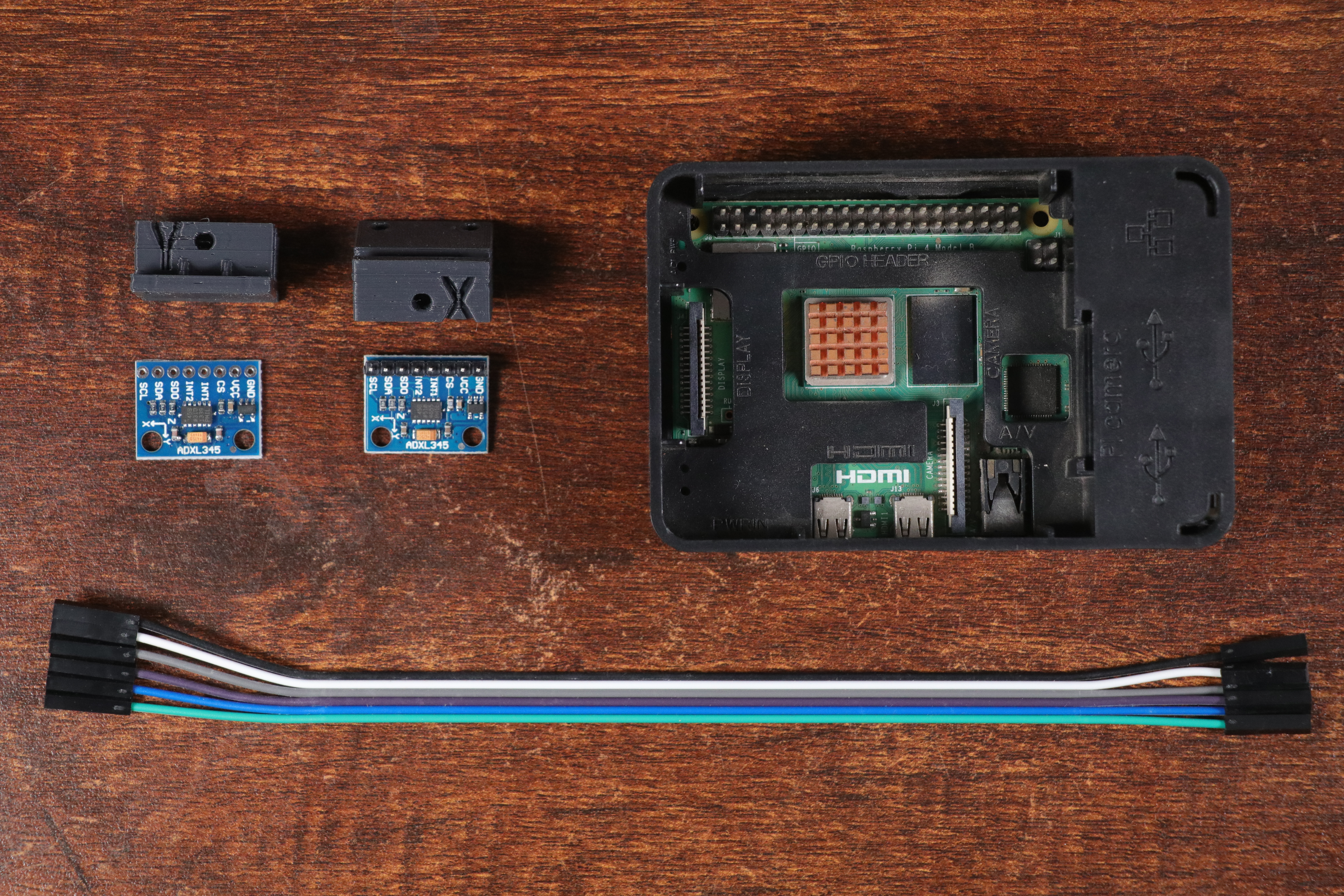
- ADXL345 accelerometers. Optionally, you can use the ADXL343 accelerometers too. This guide will use the ADXL345 version.
- Connecting wires.
- Ender 3 ADXL345 mount
Setting Up the Raspberry Pi
You need to install external software on your Pi board to measure and interpret the resonant frequencies. In this step, we’ll install NumPy and Matplotlib on your Raspberry Pi.
Numpy is a Python library that will let the Raspberry Pi and Klipper execute large and complex mathematical calculations that are necessary for computing the resonant frequencies of your 3D printer.
Whereas matplotlib will let you visualize the measured frequencies on a chart. This chart will come in handy for configuring Input shaping parameters in Klipper.
- Open PuTTY and log in to your Pi board.
- Execute the following command -
sudo apt update
sudo apt install python3-NumPy python3-matplotlib libatlas-base-dev
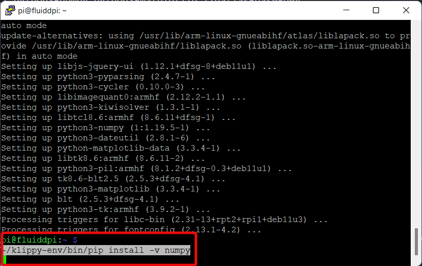
- Install NumPy in Klipper firmware by entering the following command in PuTTY
~/klippy-env/bin/pip install -v numpy
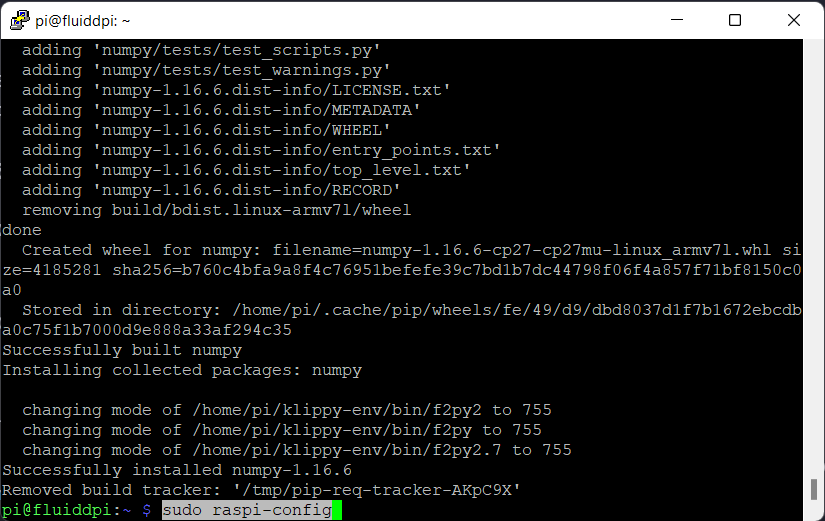
The installation process will take some time, depending on your Pi board. Once done, you’ll get a success message, and you can begin setting up Klipper to measure the resonant frequencies.
Enabling SPI Interface on Raspberry Pi
-
Enable Serial Peripheral Interface (SPI) on your Raspberry Pi. It’ll let the accelerometer communicate and exchange data with your Pi board.
-
Type sudo raspi-config in the PuTTy terminal. It’ll open up a new window inside the PuTTY interface.
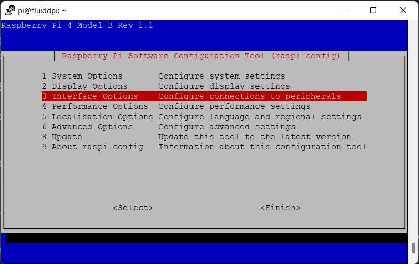
- Select the Interface options and hit enter. Navigate using the arrow keys.
- Select the SPI interface option.
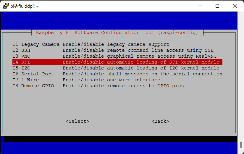
- Click on the Yes option to enable the SPI interface.

- Close the interface window.
Setting Up Raspberry Pi as Secondary MCU
In this step, we’ll be configuring the Pi as a secondary MCU for our 3D printer. It’ll allow you to directly control the 3D printer’s stepper motor via the Pi board. For a detailed explanation, refer to the microcontroller documentation on the Klipper website.
- Open the PuTTY terminal and execute the following instructions.
- Install the RC script by entering the following commands.
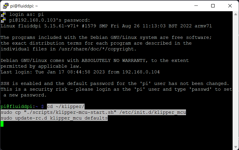
cd ~/klipper/
sudo cp "./scripts/Klipper-mcu-start.sh" /etc/init.d/klipper_mcu
sudo update-RC.d klipper_mcu defaults
- Setup and flash the MCU with Linux processor.
cd ~/Klipper/
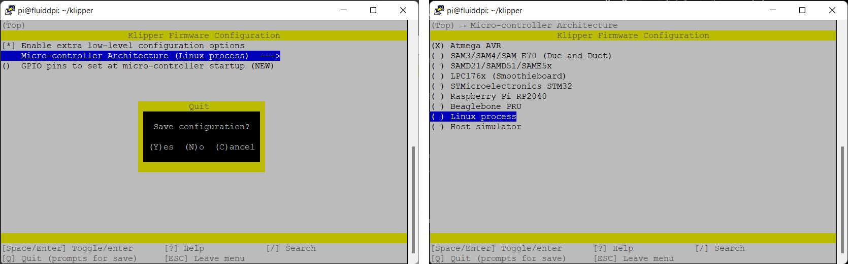
make menuconfig
- In the Klipper firmware configuration window, Select the Microcontroller as Linux process. Once selected, Press Q and save the configuration.
- Install the microcontroller code.
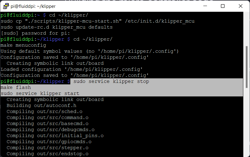
sudo service klipper stop
make flash
sudo service klipper start
- To avoid any permission access issues, type the following the code
sudo usermod -a -G tty pi
- Close the PuTTY window.
Configure Raspberry Pi and ADXL345 in Klipper Firmware
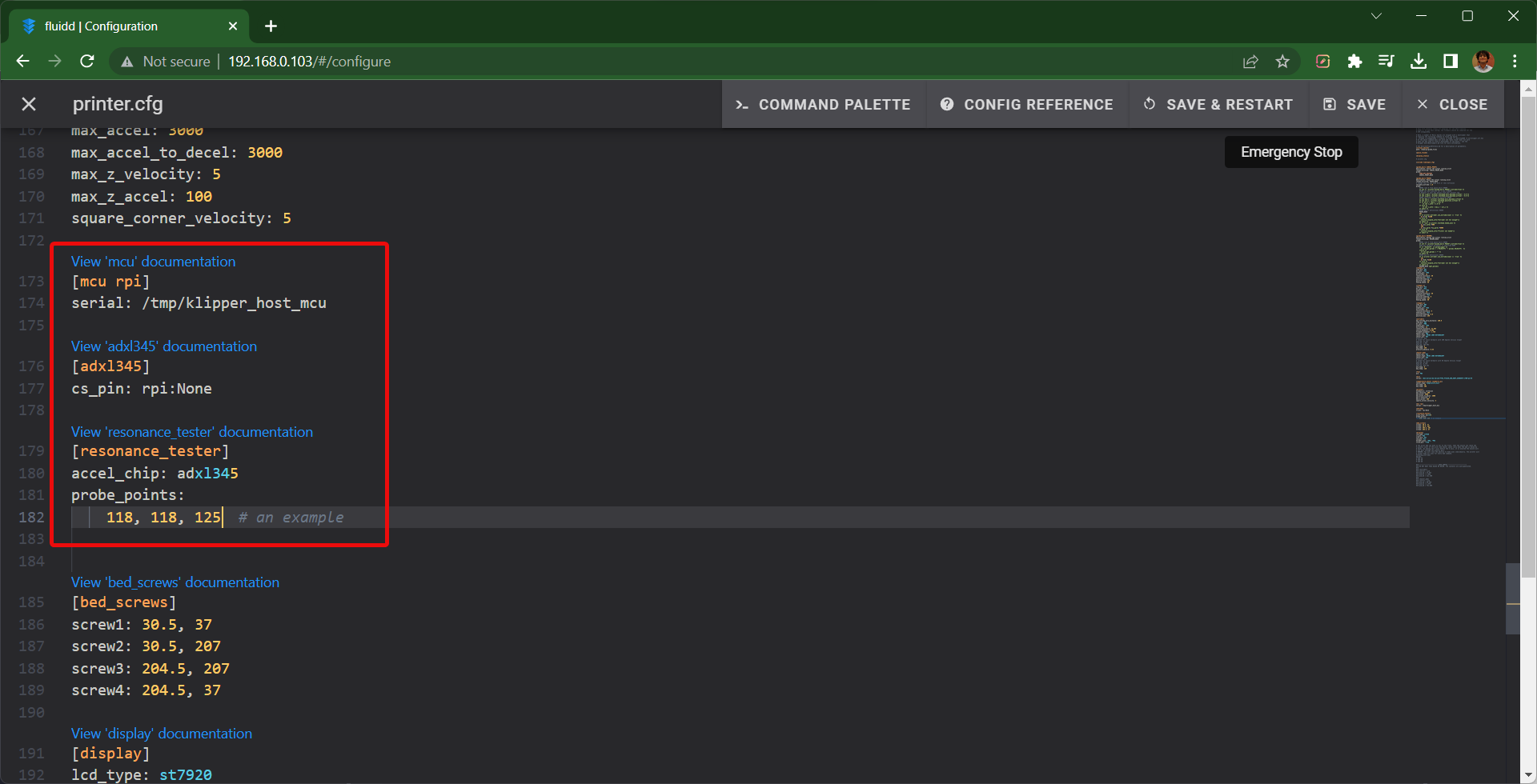
- Open printer.cfg file on your Fluidd/Mainsail interface.
- Add the following commands to the file. You can edit the probe points based on your printer’s configuration. For Ender 3, we’ll use the X, Y, and Z values as 118, 118, and 125, respectively.
[mcu rpi]

serial: /tmp/klipper_host_mcu

[adxl345]

cs_pin: RPI:None

[resonance_tester]

accel_chip: adxl345

probe_points:

    100, 100, 20  # an example
- Save and Restart the firmware.
Wiring the Raspberry Pi with ADXL345
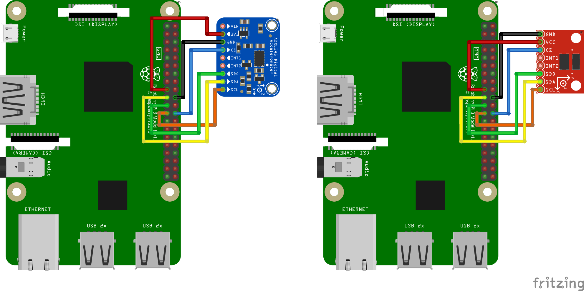 Photo Courtesy of Klipper
It’s crucial to ensure you correctly connect the Pi board with the ADXL345 to avoid any errors. Refer to the wiring guide on Klipper’s website for detailed and neatly illustrated instructions for connecting your accelerometer to the Pi board.
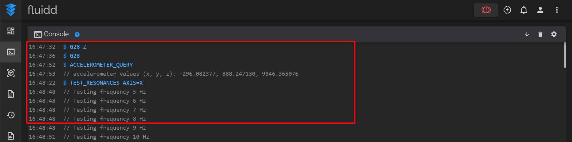
Once wired, power up everything and input the *ACCELEROMETER_QUERY* command in your Klipper console. It should display the current measurements from your accelerometer. The output will look something like this - Recv: // adxl345 values (x, y, z): 470.719200, 941.438400, 9728.196800
If you get the above output, you can now start to measure the resonant frequency for your 3D printer. But, if you get an error code, it might indicate an issue with wiring connections or your accelerometer chip. Try checking everything once again, or replace the accelerometer board.
Measuring Resonance
This step involves measuring your printer��’s resonance and determining the input shaping parameters.
- Mount the accelerometer on the X-axis carriage. Input the following command to measure the resonance on X-axis.
TEST_RESONANCES AXIS=X
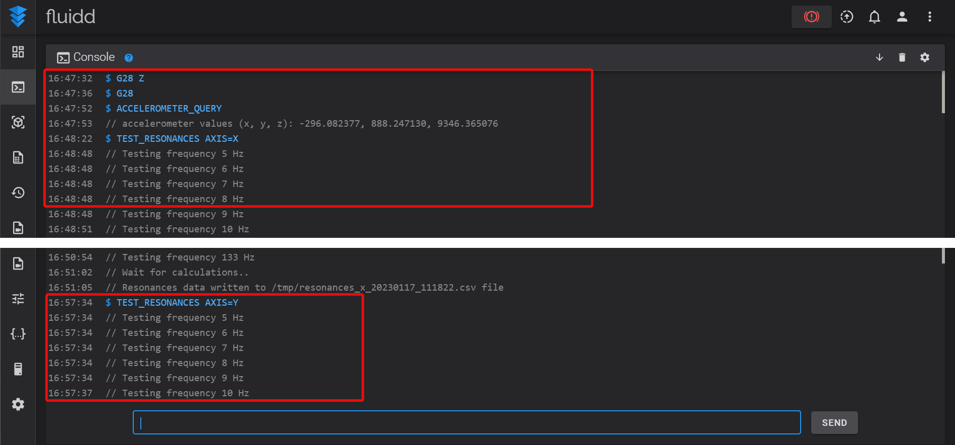
- Mount the accelerometer on the Y-axis carriage and execute the following command.
TEST_RESONANCES AXIS=Y
The resonance tests are now complete. Both tests will generate an individual CSV file that contains all the test data. You will need to run these files through the Raspberry Pi to get the actual Input Shaping parameters.
Note: While testing both axes, your printer head and build plate might vibrate significantly. While the vibrations should be within the limit, stop the test if it starts shaking too violently. As we didn’t face this issue, there was no need to test it out.
Edit the [resonance tester] section in the printer.cfg file to the below settings.
[resonance_tester]

accel_chip: adxl345

accel_per_hz: 50 # default is 75

probe_points: …
Obtaining the Resonance Test Results
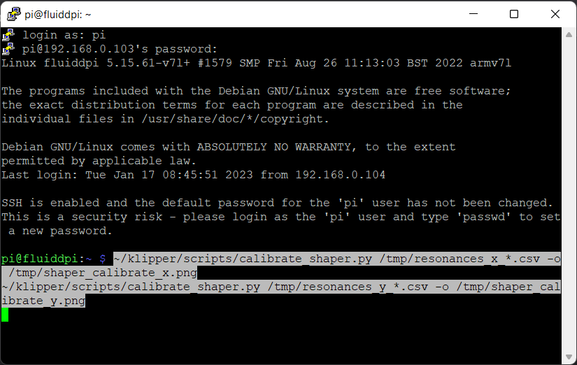
- Login to your Raspberry Pi board via the PuTTY terminal.
- Input the following commands in the PuTTY window.
~/klipper/scripts/calibrate_shaper.py /tmp/resonances_x_*.csv -o /tmp/shaper_calibrate_x.png
~/klipper/scripts/calibrate_shaper.py /tmp/resonances_y_*.csv -o /tmp/shaper_calibrate_y.png
You’ll notice two recommended shaper values and types in the PuTTY window. These are the proper Input Shaping settings.
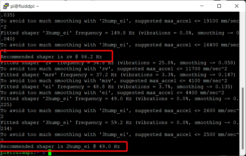
The above commands will also generate two separate image graphs detailing the various input shapers and parameters executed during the tests. These aren’t crucial but can be helpful to get a visual representation of the entire test. Follow the below steps to get these test images.
- Connect the Pi board using an FTP application. We’re using the WinSCP software.
- Log in using your Pi credentials.
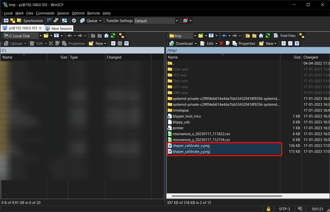
- Go to the root folder >> temp folder.
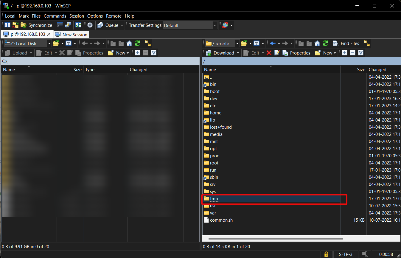
- There will be two PNG format images. Download it on your desktop and close the software.
Configuring Input Shaper values in Klipper Firmware
- Note down the recommended Input shaper frequency and type.
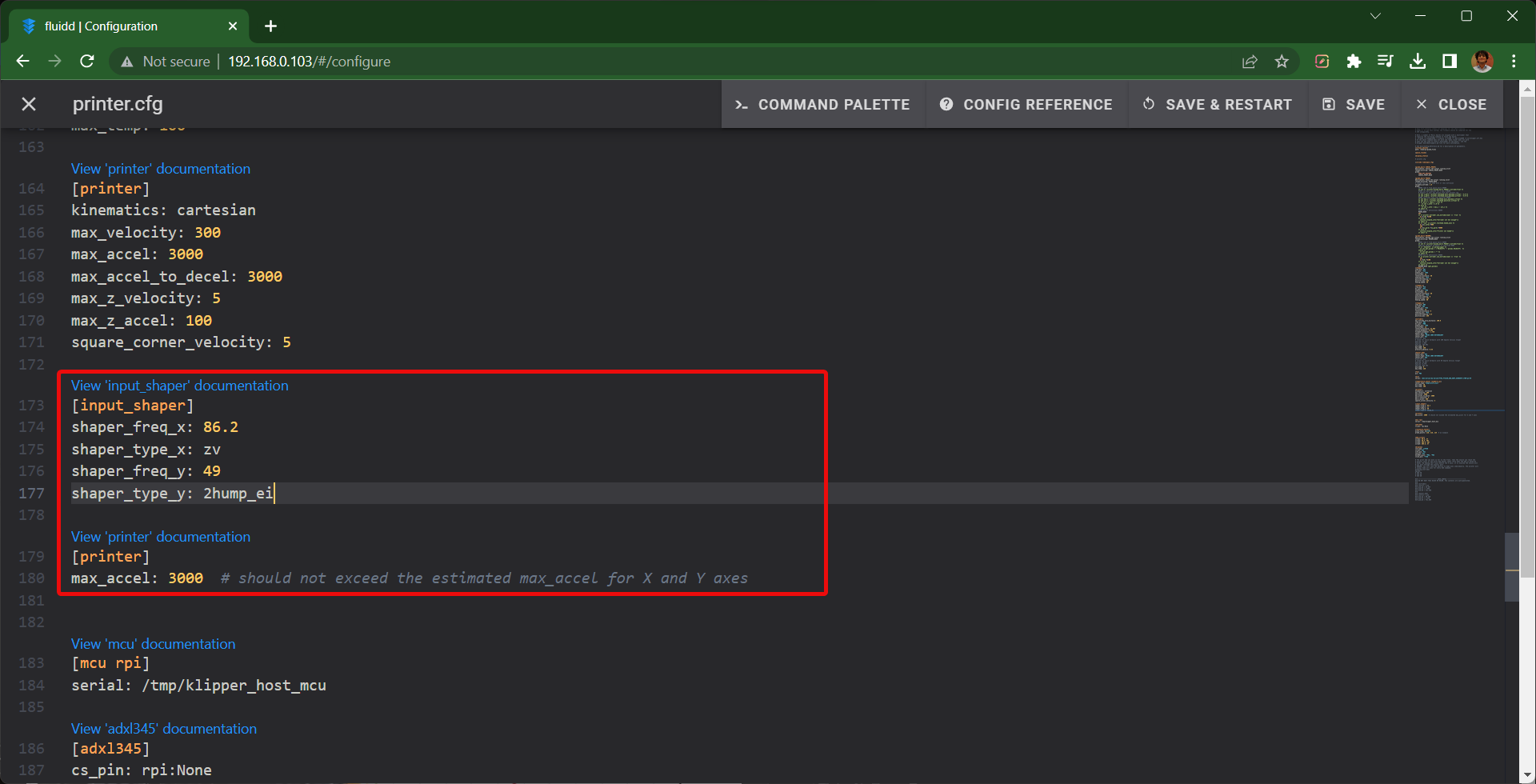
- Open the printer.cfg file and type the following commands -
[input_shaper]

shaper_freq_x: ...

shaper_type_x: ...

shaper_freq_y: 34.6

shaper_type_y: mzv

[printer]

max_accel: 3000 # should not exceed the estimated max_accel for X and Y axes
- Save and Restart firmware.
That’s it! You’ve successfully configured the Input Shaper parameters for your 3D printer using an accelerometer.
You can 3D print the ringing tower file and verify the results. You will notice a significant
reduction in your printer’s vibrations and better print quality.
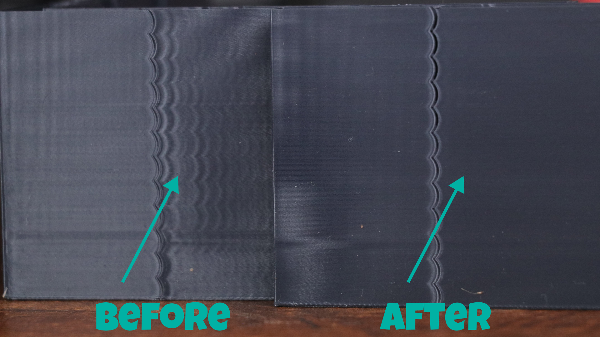
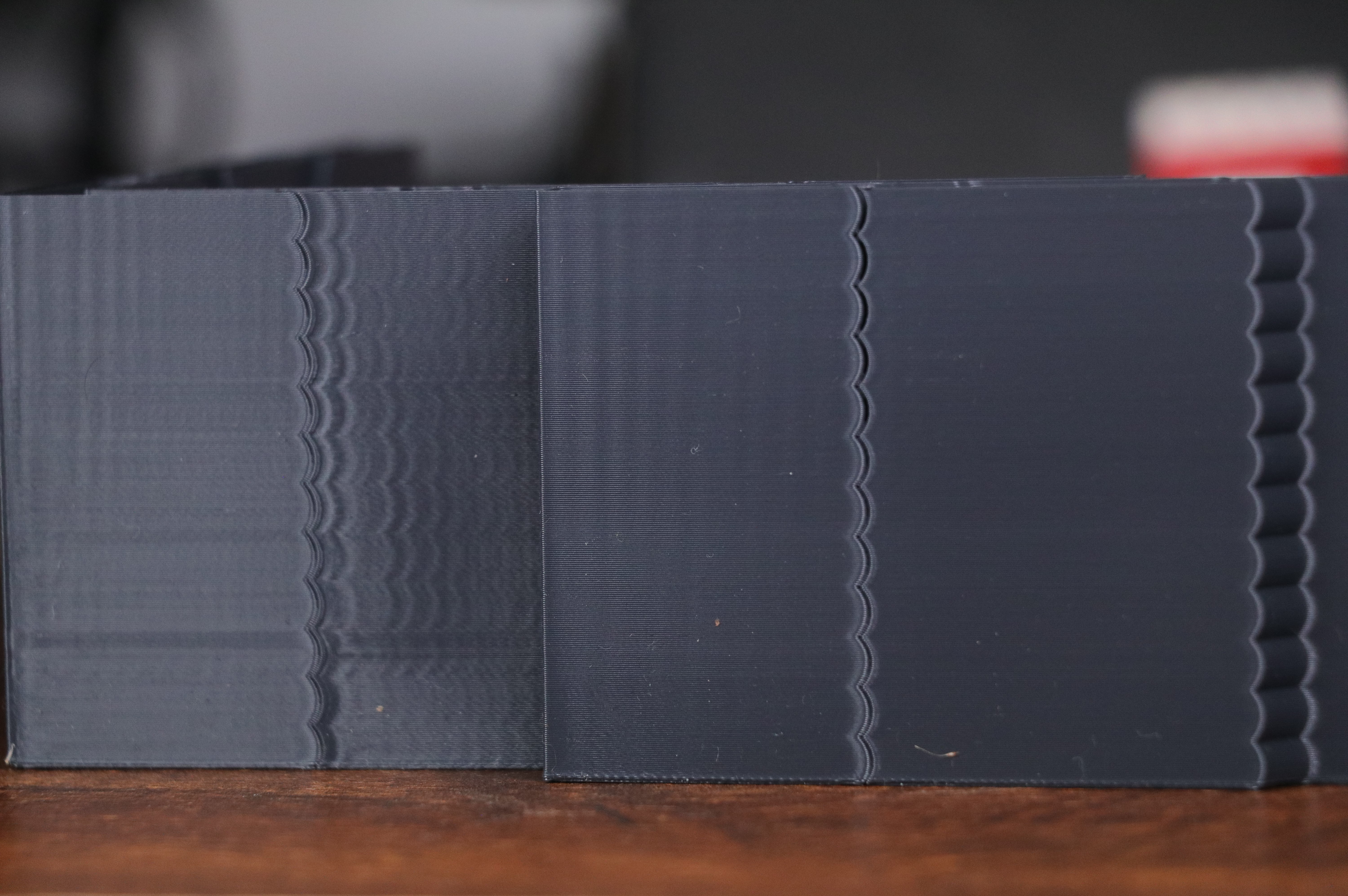
Input Shaping Results - Before and After
X-axis Input Shaping
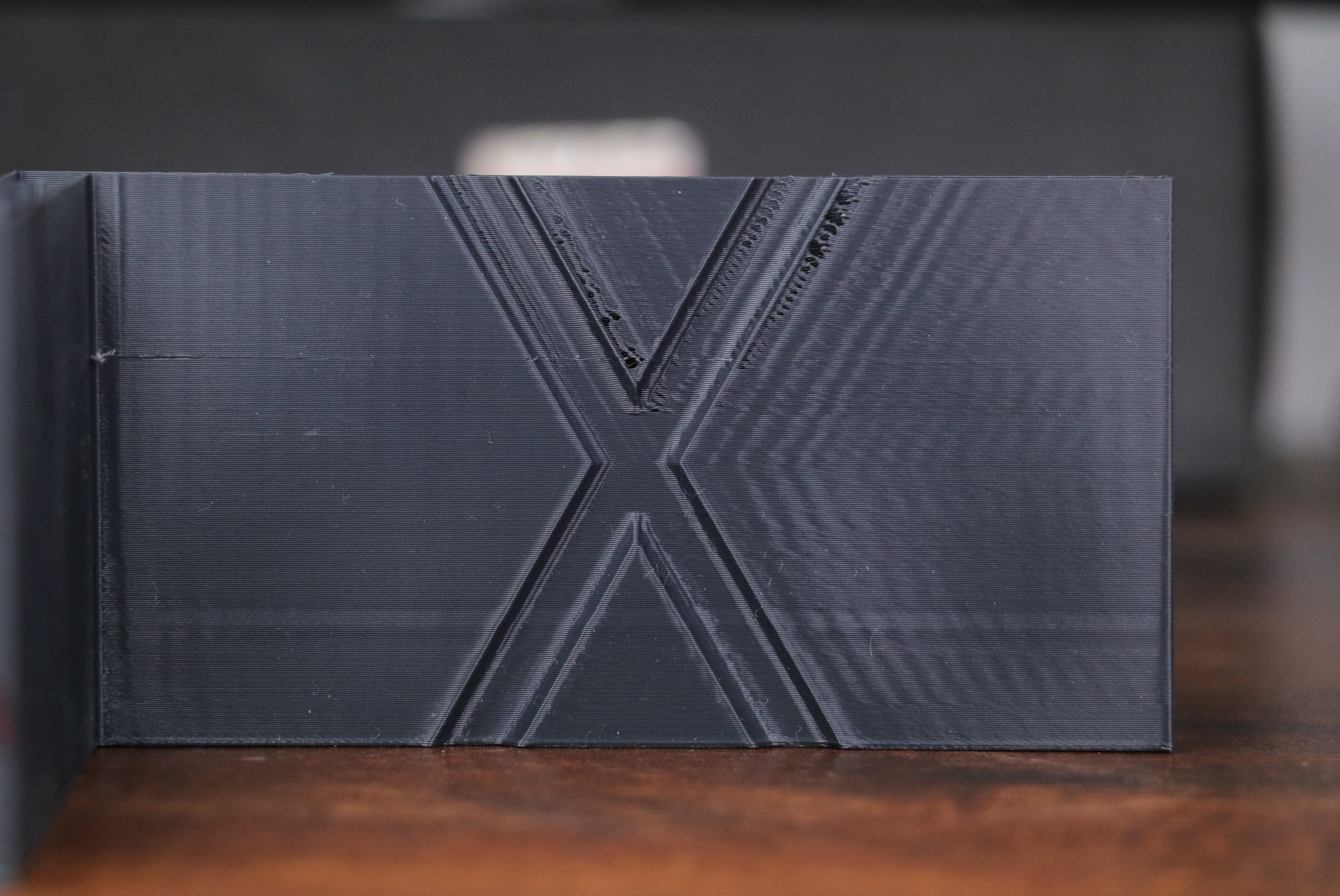
Ringing Artifacts are easily visible before Input Shaping is configured
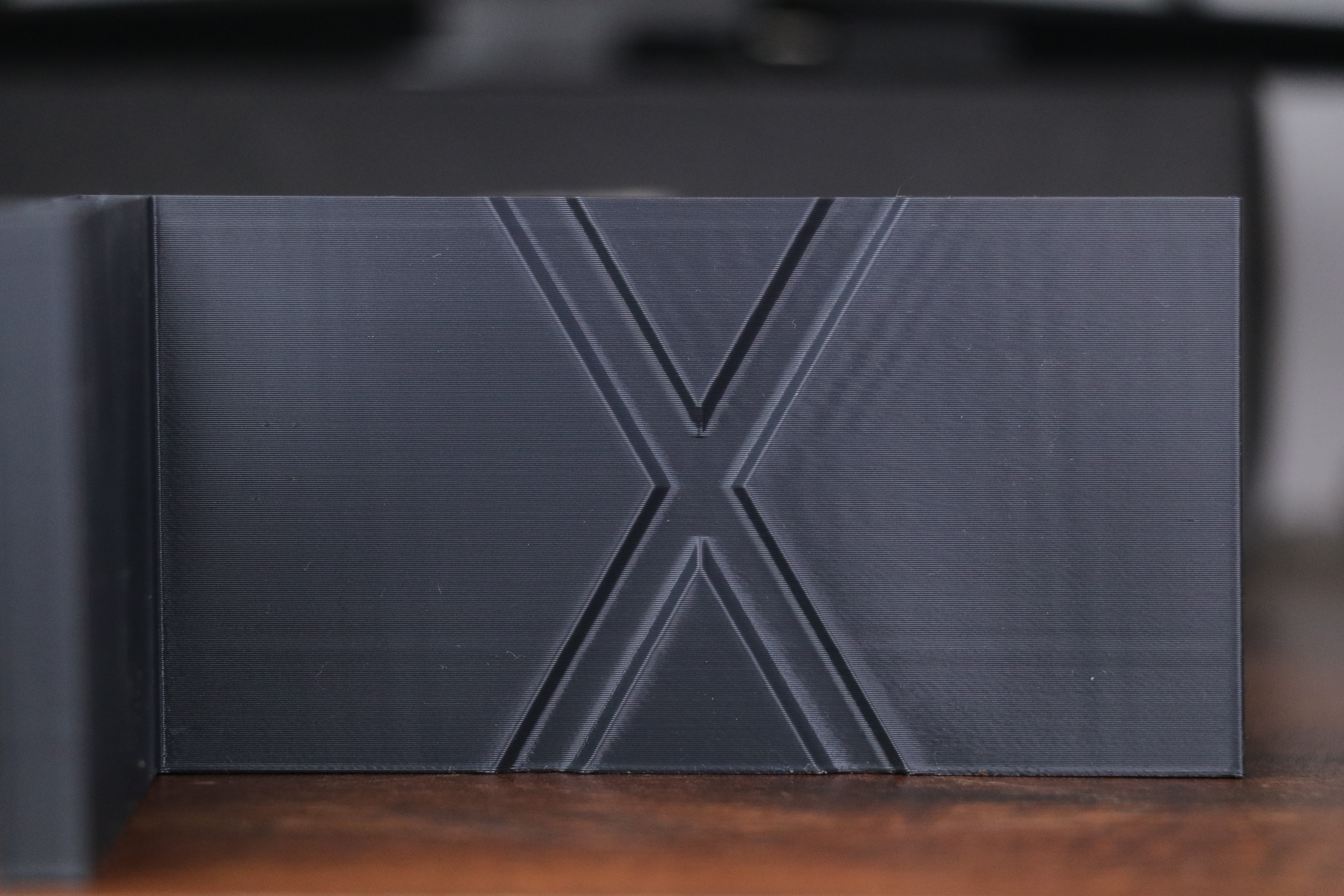
The print quality is significantly better and there are minimal ringing artifacts on surface
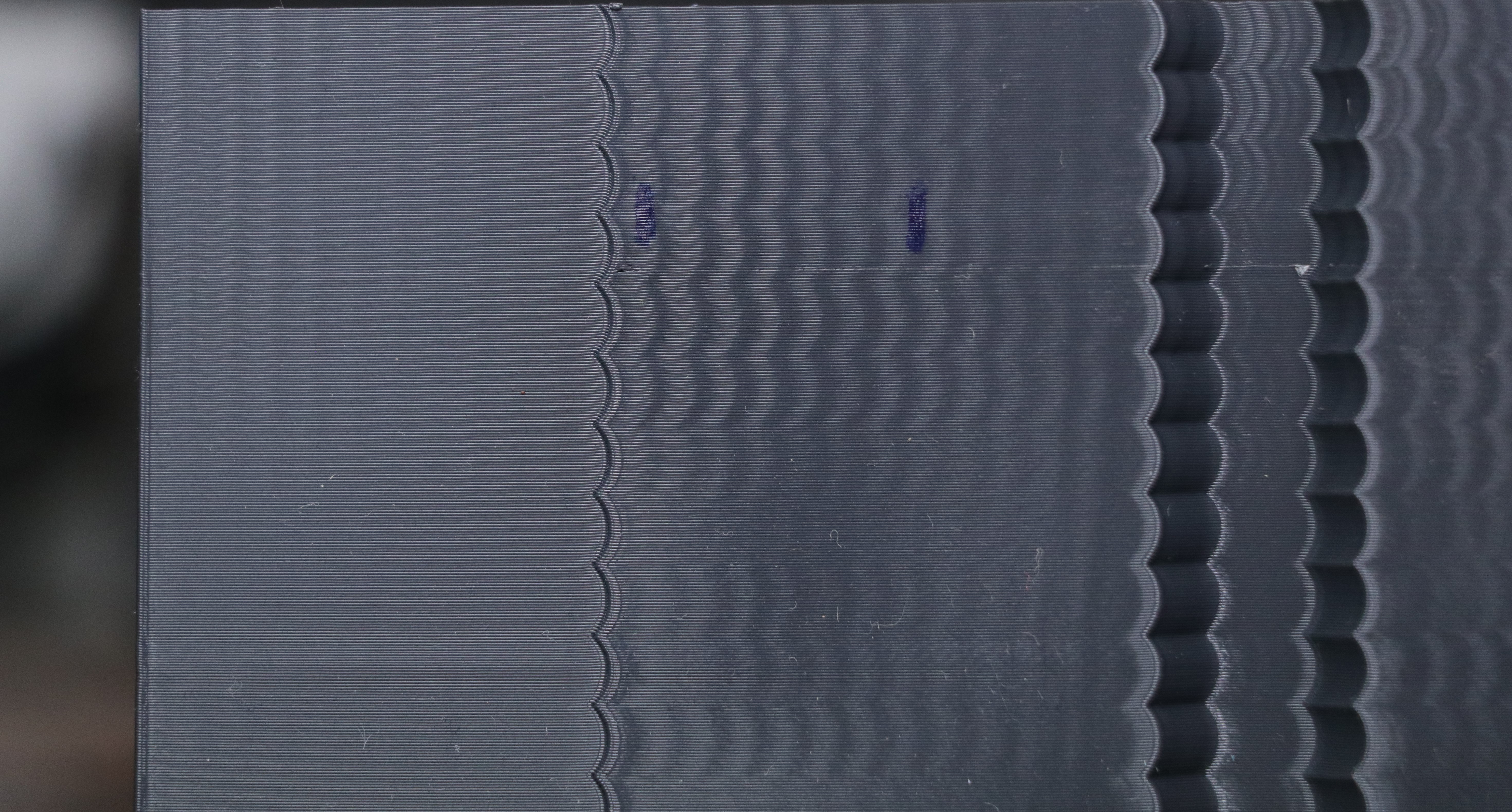
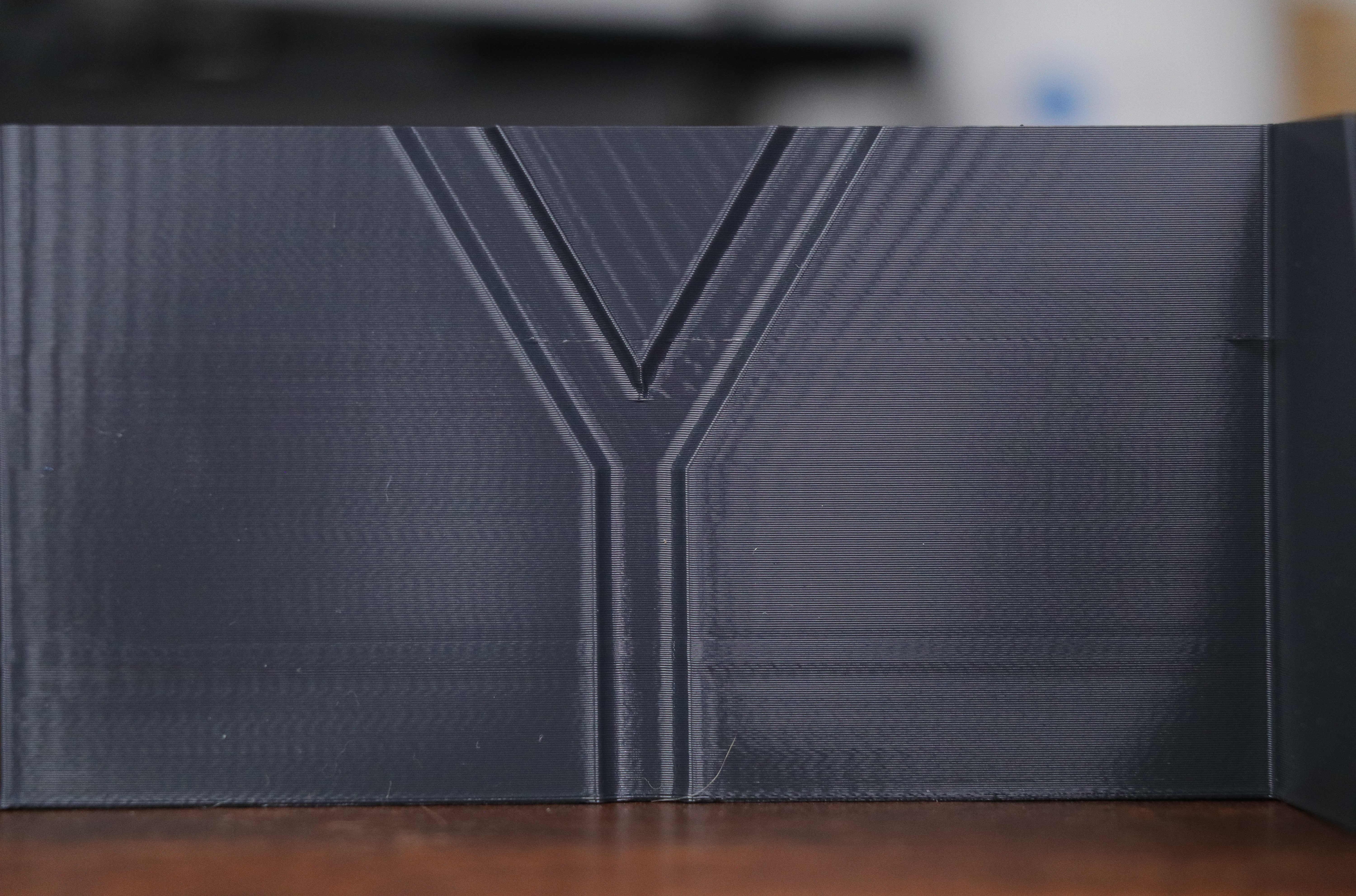
The ripples and the curves on X-axis indicate significant ghosting in prints
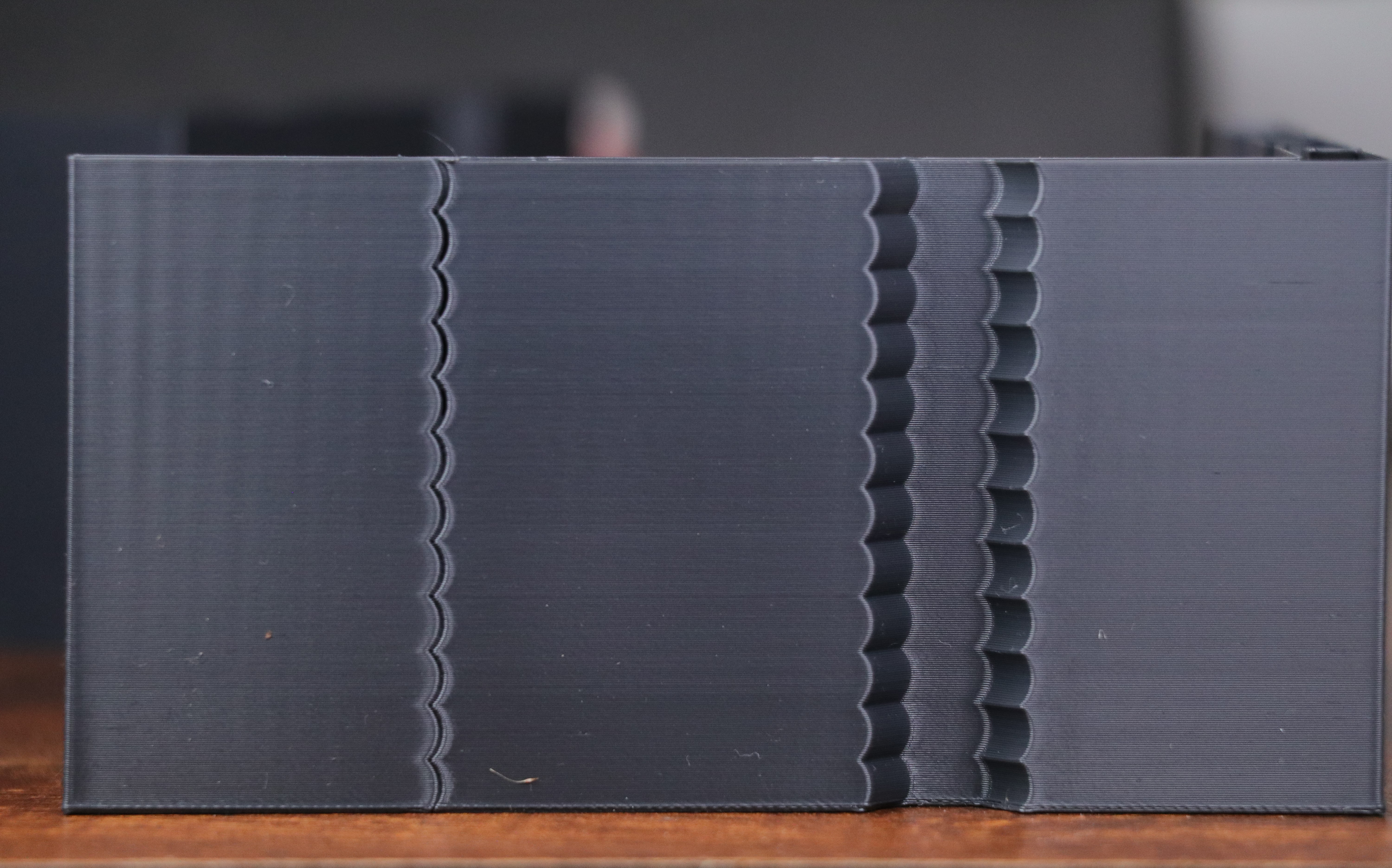
Input Shaping drastically reduces these issues, leading to a better print quality
Final Thoughts
Input Shaping in Klipper irons down the issues that are a by-product of printing at high speeds. It helps you achieve good print quality even at fast print speeds, leading to reduced print times and better printing yield.
The configuration process might seem daunting initially. But once you break it down, it's relatively straightforward to execute.
You can further fine-tune your Input Shaping parameters to optimize your print accelerations and quality. But that's a whole other topic that we'll cover in a separate guide.
Till then, let us know your views on Input Shaping in Klipper. Did you find the guide helpful? Do you have any suggestions for it? Feel free to comment below; we'll be glad to help you.
Monitor and Control Your 3D Printer from Anywhere and Get Added Peace of Mind with Obico's AI Failure Detection for Klipper
With Obico, you can control your 3D printer from anywhere in the world, on any device, in real-time. Furthermore, Obico features AI failure detection functionality to detect print failures and instantly notify you about them. Obico also automatically shoots and keeps timelapse videos for quick reference.
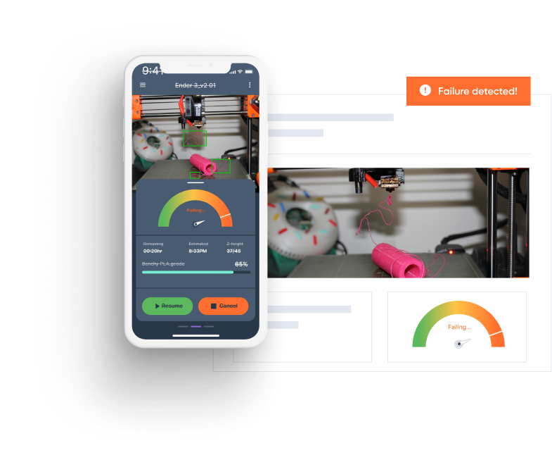
Obico can save you from several failed printing hours and loads of wasted filament material. It can be handy if you have multiple 3D printers or operate a 3D printing farm. So, along with the Klipper time-lapse, you can use Obico's AI failure detection and remote print monitoring to enhance your 3D printing experience. Obico's failure detection uses machine learning and your camera to monitor your prints for you, and if a failure is detected, Obico will notify you via sms, email, discord, etc..., or it can even stop the print for you. Get started for free).